
Intro To PTP
- Home
- >
- Intro to PTP
Our Solutions
PTP Synchronization Basics
The protocol defines synchronization messages used between a Master and Slave clock similar to the Server and Client mode used in the Network Time Protocol (NTP). The Master is the provider of time, and the Slave synchronizes to the Master. A Grandmaster is a Master that is synchronized to a time reference such as GPS. Messages in the protocol include Master sync message, Master delay response message, and the Slave clock delay request messages. In addition to the messages, the Best Master Clock (BMC) algorithm allows multiple Masters to negotiate the best clock for the network. Clock synchronization on the LAN requires at least one Master and one Slave. Multiple Slaves can synchronize to a single Master. The Master clock provides synchronization messages that the Slaves use to correct their local clocks. Precise timestamps are captured at the Master and Slave clocks. These timestamps are used to determine the network latency which is required to synchronize the Slave to the Master. There is a sync message transmitted typically every two seconds from the Master, and a delay request message from the Slave less frequently, about one request per minute.
How it works
Four timestamps are captured between the Master and Slave clock. The timestamps are required for the Slave offset calculation. The timestamps are commonly referred to as T1, T2, T3, and T4.
Two delay paths must be calculated, the Master to Slave and the Slave to Master.
First find the Master to Slave difference:
- The first timestamp is T1. It is the precise time of the sync message from the Master. This timestamp is sent in the follow-up message since the time of T1 was sampled when the sync message was transmitted on the Ethernet port.
- The second timestamp is T2. It is the precise time of the sync message as it is received at the Slave.
- The Master to Slave difference can be calculated once T1 and T2 are available at the Slave.
- Master to Slave difference = T2 - T1
Second, find the Slave to Master difference:
- The third timestamp is T3. It is the precise time of the delay request message from the Slave. The fourth timestamp is T4. It is the precise time of the delay request message when received at the Master.
- The Slave to Master difference can be calculated once T3 and T4 are available at the Slave.
- Slave to Master difference = T4 - T3

The one-way delay can be calculated once the Master to Slave and Slave to Master difference is available at the Slave:
- One way delay = (Master to Slave difference + Slave to Master difference) / 2
The offset is used to correct the Slave clock:
Offset = Master to Slave difference – One way delay
or
Offset = ((T2 – T1) – (T4 – T3)) / 2
Therefore, the following statements are true with respect to this algorithm, assuming constant network propagation delays and gradually changing operating conditions such as temperature:
The Slave clock utilizes the offset to adjust the time to agree with the Master clock. Typically, the Slave clock will use a clock tuning algorithm that can account for network propagation delays affecting the offset and the Slave clock crystal temperature and aging effect on its stability.

Transparent Switches
A transparent switch is an Ethernet switch that handles IEEE-1588 packets differently compared to a standard switch. The transparent clock measures the time that the packet is stored in the switch. It then adds the measured time into the correction field of the follow-up message. To account for the packet delay, the slave clock uses the origin timestamp and the correction field.
Network Requirements to Achieve Sub-100 Nanosecond Synchronization
Obtaining sub-100 nanosecond timing on a local area network requires an architecture that is fully IEEE-1588 compliant. The three main components are: a GPS Grandmaster clock, an Ethernet switch (transparent or boundary clock), and a PTP slave. All components must support hardware timestamping. The Grandmaster and Slave are discussed in the “PTP Implementation” section. Below is a discussion of the required Ethernet switch.
Ethernet Switches
Ethernet switches can be categorized as standard Ethernet switches and IEEE-1588 enabled Ethernet switches. A standard Ethernet switch temporarily stores packets before sending them out. The storing time of the packet is non-deterministic and network load dependent resulting in packet delay variation. The packet delay variation is the primary reason that standard Ethernet switches result in poor time synchronization even when the master and slave clock support hardware timestamping. An IEEE-1588 enabled switch is either a transparent clock or a boundary clock. Using a transparent clock or a boundary clock improves synchronization between the master and slave and ensures that the master and slave are not impacted by the affects of packet delay variation.

Boundary Clocks
A boundary clock is an Ethernet switch that handles IEEE-1588 packets differently compared to a standard switch or transparent switch. The subnets to a network must isolate PTP packets when installing a boundary clock. The boundary clock acts much like an ordinary clock on the network and becomes the master clock on the isolated subnets. The boundary clock only handles PTP packets while the standard Ethernet switches or routers handle all of the other network traffic. A slave on the isolated subnet synchronizes to the boundary clock as if it were the master clock.
High-Speed, Low-Latency Switches
High-speed low-latency switches are characterized as standard switches when it comes to timing. High-speed low-latency store and forward switches can produce very stable and accurate synchronization under light network loads; however, they will still store packets thus increasing the packet delay variation that will negatively affect impact time synchronization.
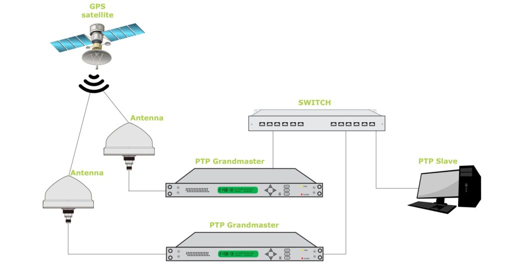
Dual-Redundant Grandmaster Clocks
Setting up the 1588-timing network with Dual-Redundant Grandmaster Clocks requires you to install and configure each of two Grandmasters according to the Best Master Clock (BMC) algorithm. The IEEE 1588-2008 (v2) standard defines the BMC algorithm.
The BMC compares the clock data of the two Grandmasters and determines the preferred clock. The clock data defines the clock characteristics and is available in the announce packet. The Grandmaster with the preferred clock data becomes the PTP Grandmaster on the network and provides timing to the Slaves. Only one PTP Grandmaster provides synchronization packets at any given time. The BMC uses the clock data to determine the Best Master Clock in the following hierarchical order:
Priority1
User configurable from 0-255. Lower value preferred.
Clock Class
Dependent on the clock being locked, in holdover, unlocked, and the epoch, either PTP or ARB. In preferred order: Locked PTP epoch, Holdover PTP epoch, Locked ARB epoch, Holdover ARB epoch, Unlocked PTP epoch, Unlocked ARB epoch.
Clock Accuracy
Dependent on the clock accuracy (Estimated Time Error), in preferred order: <25ns, <100ns, <250ns, <1us, <2.5us, <10us, <25us, <100us, <250us, <1ms, <2.5ms, <10ms, unknown.
Clock Variance
Based on the oscillator type, in preferred order: Rubidium, OCXO, or TCXO.
Priority2
User configurable from 0-255. Lower value preferred.
Unique identifier (used as a tie breaker)
The port physical MAC address. Lower value preferred.